The idea: a difference amplifier with a huge gain
An operational amplifier (op-amp) is a chip with two inputs and one output. The non-inverting input (+) and the inverting input (−) are compared, and the output is the difference multiplied by a very large open-loop gain A, typically 100 000 or more: Vout = A × (V+ − V−). The output can only swing between the two supply rails, here ±12 V, so on its own the op-amp is almost useless: a difference of 0.12 mV is already enough to drive it to a rail.
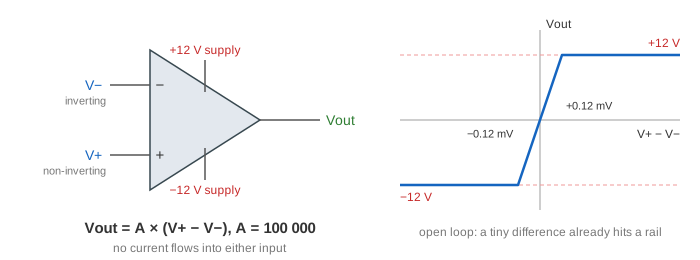
The trick is negative feedback: connect the output back to the − input through resistors. Then the circuit's gain is set by the resistors, not by A. The canvas uses R1 = 10 kΩ, Rf = 20 kΩ and a ±12 V supply. Pick a circuit and a Vin, press Solve, and each answer is added to the transfer curve on the right.
The two golden rules
An ideal op-amp obeys two rules, and with them plus Ohm's law every circuit on this page is solved in three lines.
- No current flows into the inputs: I+ = I− = 0. Real inputs draw picoamps to nanoamps.
- With negative feedback, the output makes V− = V+. If V− were a little below V+, the output would rise, which pulls V− up through the feedback, until the two meet.
Rule 2 is not exact. The output needs a small difference to exist: to give −2 V with A = 100 000, V+ − V− is only 20 µV. That is so small next to the volts in the circuit that treating it as 0 gives answers good to 0.003 %. Each Solve ends with this check. Both rules also carry a third, practical one: the output stays between the rails.
The inverting amplifier
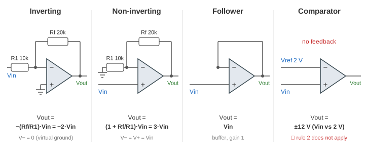
The + input is grounded, Vin drives the − input through R1, and Rf runs from the output back to the − input. By rule 2, V− = V+ = 0 V: the − input is a virtual ground, at 0 V although it is not wired to ground. Then Ohm's law gives the current in R1, I1 = Vin / R1 = 1 V / 10 kΩ = 0.1 mA for Vin = 1 V. By rule 1 none of it goes into the pin, so all 0.1 mA flows on through Rf and drops 0.1 mA × 20 kΩ = 2 V. The output sits 2 V below the virtual ground: Vout = −2 V (Demo: inverting amplifier, 1 V in, −2 V out).
In general Vout = −(Rf / R1) × Vin. The source sees an input resistance of just R1, because the far end of R1 is at 0 V.
The non-inverting amplifier and the follower
Now Vin goes straight into the + input, and Rf and R1 form a divider from the output down to ground, with the − input at the middle. Rule 2 puts V− at Vin. For Vin = 1 V, R1 has 1 V across it, so 0.1 mA flows in it; by rule 1 that current comes from the output through Rf, which drops another 2 V. Vout = 1 + 2 = 3 V (Demo: non-inverting amplifier, 1 V in, 3 V out). In general Vout = (1 + Rf / R1) × Vin, never less than 1, and with the same sign as Vin. Because the + input draws no current, the source is not loaded at all.
Take Rf = 0 and leave out R1, and the output is wired straight to the − input. This is the voltage follower or buffer: V− = V+ and V− = Vout, so Vout = Vin (Demo: voltage follower buffers 2.5 V). Its gain is only 1, but it lets a weak source, such as a sensor or a voltage divider, drive a heavy load: the current now comes from the op-amp's supply.
The comparator: no feedback
Leave out the feedback and rule 2 no longer applies. With Vin on the + input and a reference Vref = 2 V on the − input, the op-amp simply multiplies the difference by A. For Vin = 1 V it would need 100 000 × (−1 V) = −100 000 V, so it goes to the −12 V rail; for Vin = 2.5 V it goes to +12 V (Demo: comparator, 1 V and 2.5 V against 2 V). The output answers one question: is Vin above Vref?
| Circuit | Feedback | Rule 2 (V− = V+)? | Vout | Vin = 1 V |
|---|---|---|---|---|
| Inverting | Rf to the − input | Yes | −(Rf / R1) × Vin | −2 V |
| Non-inverting | Rf and R1 divider to the − input | Yes | (1 + Rf / R1) × Vin | 3 V |
| Follower | Output wired to the − input | Yes | Vin | 1 V |
| Comparator | None | No | ±12 V | −12 V |
Saturation: when rule 2 breaks
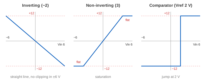
The non-inverting amplifier asked for 5 V × 3 = 15 V cannot deliver it: the output stops at the +12 V rail. The divider then gives V− = 12 V × 10 kΩ / 30 kΩ = 4 V, while V+ is still 5 V. With the output stuck, feedback has lost control and V− ≠ V+ (Demo: saturation, 5 V × 3 hits the +12 V rail). Whenever a calculation gives an output past a rail, the golden rules no longer describe the circuit. A sweep from −6 V to +6 V shows the result as a line of slope 3 that turns flat at ±4 V (Demo: sweep the non-inverting amplifier).
See also RLC Circuits for Kirchhoff's laws and Ohm's law in resistor circuits, and AC vs DC for the rectifier and the DC supplies an op-amp runs on.
What the page leaves out
Real op-amps have a finite bandwidth (the gain falls with frequency, so a gain-of-100 stage of a 1 MHz op-amp works only to about 10 kHz), a limited slew rate, an input offset voltage of microvolts to millivolts, small input bias currents, and outputs that stop a little short of the rails unless they are rail-to-rail types. Comparators in practice use positive feedback (hysteresis) so that noise near Vref does not make them chatter. Also left out: the summing amplifier, integrator, differentiator and filters, all built with the same two rules.