The idea: change the flux, get a voltage
Push a magnet into a coil of wire and a meter on the coil jumps. Stop the magnet and the meter falls back to 0, even though the magnet is still right there. Pull it out and the meter swings the other way. Michael Faraday found this in 1831: a changing magnetic field through a loop of wire pushes charge round the loop. The push is called an induced EMF (electromotive force, measured in volts), and the current it drives is an induced current.
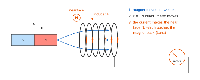
The canvas has two set-ups. In the first, a bar magnet slides along the axis of a coil of 100 turns. In the second, a loop spins between the poles of a magnet: a simple generator. The graphs on the right plot the flux through one turn and the EMF against time.
Magnetic flux
The magnetic flux through a loop counts how much magnetic field passes through it. For a flat loop of area A in a uniform field B it is Φ = B·A·cos θ, where θ is the angle between the field and the loop's normal (the arrow sticking straight out of the loop's face). The unit is the weber: 1 Wb = 1 T·m². The flux is largest when the field goes straight through the loop (θ = 0°) and 0 when the field runs along the loop's face (θ = 90°). A coil of N turns links the flux N times.
On the canvas, the flux through one turn of the coil is 0.006 mWb with the magnet 8 cm away and 0.4 mWb with the magnet at the centre. The sign says which way the field points through the coil: positive to the right.
Faraday's law
The induced EMF equals the rate at which the flux changes, times the number of turns:
ε = −N · dΦ/dtOnly the change counts. A magnet held still inside the coil gives the largest flux and 0 V (Demo: push the N pole in, hold, pull it out). The EMF is largest where the flux changes fastest with position: on the canvas 1 cm before the centre, where ε = −1.72 V at 1 m/s. Right at the centre the flux is at its peak, so for an instant it is not changing and ε = 0 even though the magnet is moving.
| What happens | Flux Φ | EMF ε |
|---|---|---|
| Magnet far away, at rest | almost 0, steady | 0 |
| N end pushed in | rising, positive | negative, peak −1.72 V |
| Magnet held at the centre | 0.4 mWb, steady | 0 |
| N end pulled out | falling, positive | positive, peak +1.72 V |
| Same, at 2 m/s | same change, half the time | twice as big, ±3.44 V |
Lenz's law: the minus sign
The minus sign in Faraday's law is Lenz's law: the induced current flows so that its own magnetic field opposes the change of flux that made it. When the N end comes in, the flux to the right grows, so the induced current makes a field to the left. That field turns the coil's left face into an N pole, which pushes back on the approaching N end. When the N end leaves, the flux shrinks, so the current reverses and the left face becomes an S pole, which pulls on the leaving magnet. On the canvas the blue arrow is the magnet's field in the coil and the orange arrow is the induced current's field; the orange arrow always points against the change of the blue one.
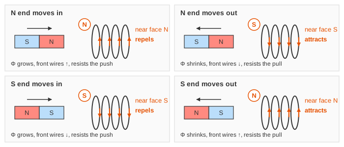
Flip the magnet so its S end faces the coil and every sign flips too: the flux is negative, and pushing in now gives a positive EMF (Demo: S pole first, the current reverses). Push the magnet right through the coil and you get one pulse as it comes in and an opposite pulse as it leaves the other side (Demo: right through the coil, two opposite pulses).
Lenz's law is energy conservation. If the coil attracted an approaching magnet, the magnet would speed up, make more current, be pulled harder, and you would get energy from nothing. Instead you must push the magnet against the coil's force, and that work is what becomes electrical energy (and heat in the wire).
Faster means more voltage
Move the magnet twice as fast and the flux makes the same change in half the time, so the EMF is twice as large for half as long (Demo: twice as fast, twice the EMF). The area under the EMF curve, ∫ε dt = −N·ΔΦ, depends only on where the magnet starts and ends, not on how fast it goes. More turns, a stronger magnet or a faster movement all give a bigger EMF.
The generator: a loop spinning in a field
Instead of moving a magnet, spin a loop in a steady field. The loop's angle θ grows at a steady rate ω = 2π·f, so the flux follows a cosine and the EMF a sine:
Φ = B·A·cos(ωt) ε = −N·dΦ/dt = N·B·A·ω·sin(ωt)On the canvas N = 50 turns, A = 0.01 m², B = 0.2 T, so the peak flux is 2 mWb per turn. At 50 Hz, ω = 314 rad/s and the peak EMF is 50 × 0.2 × 0.01 × 314 = 31.4 V. One turn gives one full AC cycle (Demo: generator, one turn = one AC cycle). Spinning twice as fast doubles both the frequency and the peak, to 62.8 V at 100 Hz (Demo: generator spun twice as fast).
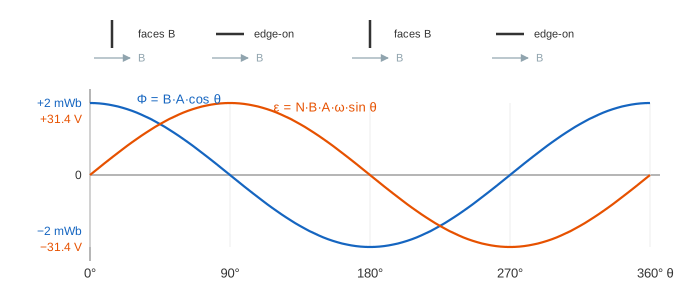
The surprise is where the EMF peaks: when the loop is edge-on to the field and the flux through it is 0. That is when the flux is changing fastest, because the loop's sides are cutting straight across the field lines. When the loop faces the field the flux is largest but the sides slide along the field lines, so ε = 0 and the current reverses. A real generator connects the spinning loop to the outside through slip rings and brushes. Turning it under load is hard work, because the current in the loop feels a force that opposes the rotation: Lenz again.
Where induction is used
| Device | What changes the flux |
|---|---|
| Power-station generator, bicycle dynamo | A coil and a magnet turning past each other |
| Transformer | An AC current in the other coil on the same core |
| Induction cooktop, wireless phone charger | A coil fed with AC at tens of kHz under the pan or phone |
| Electric guitar pickup | The steel string vibrating above a magnet and coil |
| Eddy-current brake (trains, roller coasters) | A metal plate moving past magnets; Lenz's law slows it |
See also Electric and Magnetic Fields for Faraday's law as one of Maxwell's equations, AC vs DC for why a transformer needs AC, and RLC Circuits for self-induction in a coil. Far from any coil, a changing B makes E and a changing E makes B, so the two fields can travel on their own as light: see Electromagnetic Waves.
What the page leaves out
The magnet's flux uses an on-axis dipole formula, as if every turn of the coil sat at its centre; a real coil has length and the field spreads. The EMF shown is the open-circuit value: the page does not compute the current, the coil's resistance and self-inductance, or the force on the magnet. The generator has no load, no slip rings drawn and a perfectly uniform field. Motional EMF (v × B on a moving wire) and the electric field that a changing B creates in empty space are only mentioned.