The idea: three rules solve any resistor circuit
A battery pushes charge round a circuit. The push is the voltage V, measured in volts. The flow is the current I, in amperes. A resistor holds the flow back, and how much it does is its resistance R, in ohms (Ω). Three rules are enough to find every voltage and current in a circuit made of batteries and resistors: Ohm's law for each part, and Kirchhoff's two laws for how the parts join.
The canvas uses one small circuit: a 12 V battery, R1 = 2 Ω in series, then R2 = 6 Ω and R3 = 3 Ω side by side (in parallel) down to the battery's other side. The points where wires join are nodes; A is the top of R2 and R3, B the bottom.
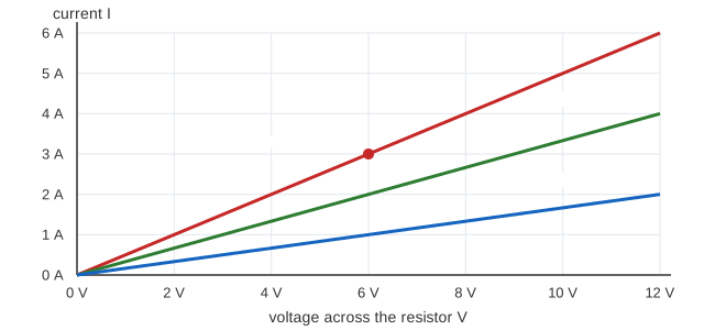
Ohm's law: I = V / R
The current through a resistor is the voltage across it divided by its resistance: V = I × R, or I = V / R. Double the voltage and the current doubles; double the resistance and it halves. "Across" matters: what drives the current is the difference in voltage between the resistor's two ends. R1 has 12 V on one end and VA on the other, so I1 = (12 − VA) / 2. The table on the canvas lists V across and I = V / R for every part.
Kirchhoff's current law (KCL)
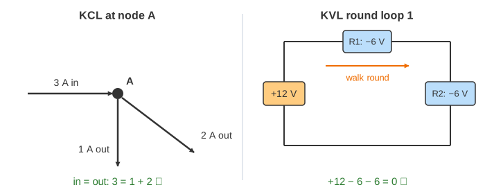
Charge is not made, destroyed or stored at a node, so the current into a node equals the current out of it. At A, the 3 A that comes through R1 splits into 1 A through R2 and 2 A through R3 (Demo: KCL, 3 A into A = 1 A + 2 A out). Both branches have the same voltage across them, so by Ohm's law the smaller resistor takes the bigger share: 3 Ω takes twice what 6 Ω takes. Make R3 = 1.5 Ω and it takes 3 A of 3.75 A (Demo: R3 = 1.5 Ω, the smaller resistor takes more).
Kirchhoff's voltage law (KVL)
Voltage is like height. Walk round any closed loop and you come back to the same height, so the rises and drops round a loop add to 0. Loop 1 goes up 12 V through the battery, down 6 V through R1 and down 6 V through R2: +12 − 6 − 6 = 0. Loop 2 has no battery: down 6 V through R3 and back up 6 V through R2 against its current (Demo: KVL, drops around both loops add to 0). That is why parts in parallel always have the same voltage across them.
| Law | Says | Because | On the canvas (R3 = 3 Ω) |
|---|---|---|---|
| Ohm | V = I × R for each resistor | the material's resistance | R1: 6 V = 3 A × 2 Ω |
| KCL | Σ I in = Σ I out at a node | charge is conserved | 3 A = 1 A + 2 A at A |
| KVL | Σ V round a loop = 0 | energy is conserved | +12 − 6 − 6 = 0 |
Solving with node equations
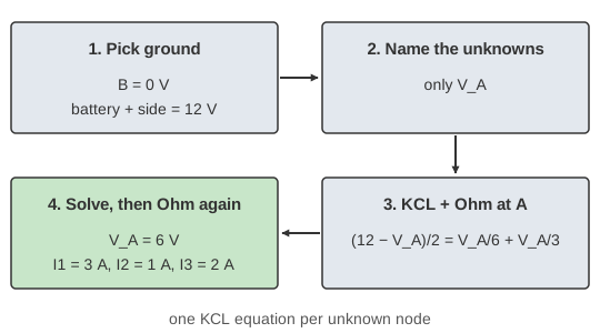
The node method (nodal analysis) turns the three rules into equations you can solve (Demo: solve the network with one node equation):
- Pick a ground node and call it 0 V. Here it is B, the battery's − side, so the + side is 12 V.
- Name each other unknown node voltage. Here only VA.
- Write KCL at each unknown node, with every current from Ohm's law: (12 − VA)/2 = VA/6 + VA/3.
- Solve: 6 = VA × (6/12 + 2/12 + 4/12), so VA = 6 V. Then Ohm's law gives each current: I1 = 3 A, I2 = 1 A, I3 = 2 A.
1/R is called the conductance G, in siemens. In conductances the equation reads VA × (G1 + G2 + G3) = 12 × G1: the conductances of parallel branches simply add. The battery sees 12 V ÷ 3 A = 4 Ω, which is R1 plus R2 and R3 in parallel: 2 + (6 × 3)/(6 + 3) = 4 Ω.
| R3 | VA | I1 | I2 | I3 | Battery sees |
|---|---|---|---|---|---|
| 3 Ω | 6 V | 3 A | 1 A | 2 A | 4 Ω |
| 6 Ω | 7.2 V | 2.4 A | 1.2 A | 1.2 A | 5 Ω |
| 1.5 Ω | 4.5 V | 3.75 A | 0.75 A | 3 A | 3.2 Ω |
| open | 9 V | 1.5 A | 1.5 A | 0 A | 8 Ω |
An open branch
An open branch (a broken wire or an open switch) carries no current, so it drops out of the KCL equation. With R3 open, R1 and R2 are simply in series: 12 V ÷ 8 Ω = 1.5 A, and VA rises to 9 V. KVL still holds round loop 2: the open gap has the full 9 V across it with no current through it (Demo: open R3, all current goes through R2). That is why touching both sides of an open switch can still be dangerous.
Bigger networks
With n unknown nodes you write n KCL equations and get n linear equations in n unknowns, usually written as a matrix G·v = i and solved by Gaussian elimination. Circuit simulators such as SPICE do exactly this. The other classic method, mesh analysis, writes KVL round each loop with an unknown loop current instead. See also RLC Circuits, where Kirchhoff's laws meet capacitors and inductors, and AC vs DC for the I²R loss in a power line.
What the page leaves out
Real parts: a battery's internal resistance, wire resistance, and resistors that change value as they heat up. Power (P = V × I: the battery gives 36 W, R1 takes 18 W, R2 6 W, R3 12 W). Current sources, dependent sources, superposition and Thévenin equivalents. Capacitors, inductors and AC, where Ohm's law becomes V = I × Z with a complex impedance. Arrows show conventional current, + to −; electrons actually move the other way.