The idea: drop every point straight onto the line
Pick a line L through the origin. The orthogonal projection onto L sends each point v to the point of L right "under" it: drop a perpendicular from v to L, and the foot of that perpendicular is the shadow Pv. Think of the sun straight overhead L: every point casts its shadow at a right angle onto the line.
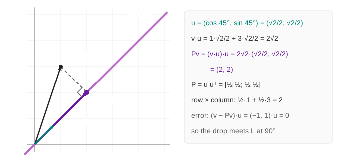
On the canvas, the purple line is L, the black arrow is v, the dashed segment is the drop, and the dark purple arrow is Pv (Demo: drop at a right angle onto y = x). The panel A point v and its shadow Pv works the numbers out.
The formula: P = u uᵀ
Let u = (cos θ, sin θ) be a unit vector along L. The shadow of v is a multiple of u, and the multiple is the dot product v·u: because |u| = 1, v·u is exactly how far along L the foot lies. So
Entry (i, j) of P is ui·uj. As always, column 1 is where î lands and column 2 is where ĵ lands, and both are points of L. Example: for y = x, u = (√2/2, √2/2), P = [½ ½; ½ ½], and for v = (1, 3): v·u = 4·√2/2 = 2√2, so Pv = 2√2·(√2/2, √2/2) = (2, 2). Row times column gives the same: ½·1 + ½·3 = 2 twice.
| L | θ | u | P |
|---|---|---|---|
| x-axis | 0° | (1, 0) | [1 0; 0 0]: keep x, drop y |
| y-axis | 90° | (0, 1) | [0 0; 0 1]: keep y, drop x |
| y = x | 45° | (√2/2, √2/2) | [½ ½; ½ ½] |
| 30° line | 30° | (√3/2, ½) | [¾ √3/4; √3/4 ¼] |
| 60° line | 60° | (½, √3/2) | [¼ √3/4; √3/4 ¾] |
| y = −x | 135° | (−√2/2, √2/2) | [½ −½; −½ ½] |
The x-axis case is the simplest: [1 0; 0 0]·(2, 1) = (2, 0). The shadow keeps x and forgets y (Demo: project onto the x-axis: drop y). Note that u and −u give the same P: only the line matters, not its direction.
The plane flattens: det = 0, rank 1, no inverse
Apply P to every point at once and the whole plane collapses onto L. On the canvas each point slides straight toward L along its own perpendicular (the in-between grids are ½I + ½P), and at the end the blue grid, the shaded unit square and the orange F all lie on L. The grey ghost keeps the F and the square as they were.
The unit square ends up as a piece of a line, so its area is 0, and the determinant says the same: det P = cos²θ·sin²θ − (cos θ sin θ)² = 0. For 30°: ¾·¼ − √3/4·√3/4 = 3/16 − 3/16 = 0 (Demo: the plane flattens: det = 0). All outputs lie on one line, so the rank is 1.
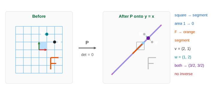
Area 0 means no inverse, and you can see why: many points have the same shadow. On y = x, v = (2, 1) and w = (1, 2) both land on (3/2, 3/2); so does every point of the perpendicular line through them. To undo P, (3/2, 3/2) would have to go back to all of them at once. The formula agrees: P−1 = (1/det)·[…] needs 1/0 (Demo: many points, one shadow: no inverse). Projection forgets the distance from L, and that information is gone.
Projecting twice changes nothing: P² = P
After one projection every point is on L, and a point of L is its own shadow. So a second projection moves nothing: P2 = P. In symbols, P2 = u(uᵀu)uᵀ = u·1·uᵀ = P, since uᵀu = |u|² = 1. Press Project Plane twice, or run Demo: project twice: nothing changes (P² = P): the matrix panel checks one entry of P·P, and the grid does not move. A matrix with P2 = P is called idempotent.
Eigenvectors: λ = 1 along the line, λ = 0 across it
Two directions are special. A vector on L is already its own shadow: Pu = u, an eigenvector with eigenvalue λ = 1. A vector perpendicular to L, n = (−sin θ, cos θ), drops straight onto the origin: Pn = 0, eigenvalue λ = 0. That perpendicular line is the null space of P (Demo: eigenvectors: on the line ×1, across ×0).
| Direction | What P does | λ |
|---|---|---|
| along L (u) | keeps it | 1 |
| across L (n) | sends it to 0 (null space) | 0 |
Every v splits as (v·u)u + (v·n)n. P keeps the first part and drops the second. The eigenvalues also give the other facts: det = 1·0 = 0, trace = 1 + 0 = 1 (cos²θ + sin²θ), and P2 = P because 1² = 1 and 0² = 0.
The error is perpendicular: closest point and least squares
The dashed segment is the error e = v − Pv. It is perpendicular to L: (v − Pv)·u = v·u − (v·u)(u·u) = 0. That makes Pv the point of L closest to v: any other point of L is the hypotenuse of a right triangle, so it is farther away. This is the heart of least squares, which projects a data vector onto the column space of a matrix: P = A(AᵀA)−1Aᵀ, which is u uᵀ when A is the single column u. Projecting onto the top principal direction in PCA is the same move.
A projection also gives the reflection across L: go to the foot, then the same distance again, so the mirror image of v is 2Pv − v and the reflection matrix is 2P − I. For y = x that is [0 1; 1 0]. In Demo: many points, one shadow, w = 2Pv − v is exactly v's mirror image.
See also the overview Linear Transformations and the other pages of this family: Rotation Matrix, Reflection Matrix, Scaling Matrix, Shear Matrix and Projection Matrix (this page).
What the page leaves out
Only orthogonal projections onto a line through the origin in 2D are drawn, for six angles with exact entries. Left out: oblique projections (drop along a slanted direction; still P2 = P but not symmetric), projection onto a plane in 3D or onto a subspace of dimension k (P = QQᵀ with orthonormal columns in Q), the general least-squares formula worked out, Gram–Schmidt, and the perspective "projection" of computer graphics, which is not a linear map of the plane.