The idea: not too late, not too early
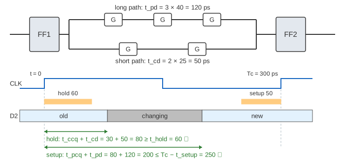
Almost every digital circuit is built from one pattern: a register (a row of flip-flops), some combinational logic, and another register, all driven by one clock. At a rising edge the first register (FF1, the launch register) puts new data on its output. The data runs through the logic and must be waiting at the second register (FF2, the capture register) when the next edge comes.
Two things can go wrong. The data can arrive too late for the next edge: a setup violation. Or a fast path can deliver it too early, while FF2 is still capturing the old data at the same edge that launched it: a hold violation. Timing analysis checks both with a few numbers from the data sheets.
The numbers
The page uses the flip-flop and gate numbers of the worked example in Harris & Harris, section 3.5. A propagation delay (t_pd, t_pcq) is the longest time until an output is stable; a contamination delay (t_cd, t_ccq) is the shortest time until it starts to change.
| Part | Parameter | Meaning | Value |
|---|---|---|---|
| Flip-flop | t_pcq | clock edge to Q stable | 80 ps |
| t_ccq | clock edge to Q starts changing | 30 ps | |
| t_setup | D must be stable this long before the edge | 50 ps | |
| t_hold | D must stay stable this long after the edge | 60 ps | |
| Gate or buffer | t_pd | input to output stable | 40 ps |
| t_cd | input to output starts changing | 25 ps |
The logic between the registers has a long (critical) path, which sets its t_pd, and a short path, which sets its t_cd. The canvas draws one of each.
The setup time constraint
The data leaves FF1 at most t_pcq after the edge, needs at most t_pd to get through the logic, and must be at FF2 t_setup before the next edge, one period Tc later:
With 3 gates: 80 + 120 + 50 = 250 ps, so a clock of 300 ps leaves a setup slack of +50 ps, and the fastest clock is 250 ps (4 GHz). (Demo 1: a path that meets timing.) With 6 gates the data needs 370 ps and a 300 ps clock fails by 70 ps. Two fixes:
- A slower clock. Tc = 400 ps gives +30 ps of slack, but every operation now takes longer. (Demo 2.)
- Pipelining. A register in the middle splits the 6 gates into two stages of 3. Each stage needs 250 ps again, so the 300 ps clock works. A result takes 2 cycles to get through, but a new one finishes every cycle. (Demo 3; see The MIPS Pipeline.)
Making the logic itself faster, for example a carry-lookahead adder instead of ripple carry, is the third fix: see the critical path on Arithmetic Circuits and gate delays on Combinational Logic.
The hold time constraint
At the same edge that launches new data from FF1, FF2 is capturing the old data, and it needs that old data to stay put for t_hold. The new data can reach FF2 as soon as t_ccq + t_cd after the edge, through the shortest path:
Tc does not appear: a slower clock cannot fix a hold violation, which is why a chip with one is broken at every speed. With a short path of 1 gate: 30 + 25 = 55 < 60, hold slack −5 ps ✗. The fix is to add buffers to the short path: one buffer gives 30 + 50 = 80 ≥ 60, slack +20 ps ✓. The buffer is not on the long path, so setup does not change. (Demo 4: hold violation, add a buffer.)
Clock skew
The clock is a wire too, and it does not reach every flip-flop at the same moment. Say CLK2 at FF2 arrives δ later than CLK1 at FF1 (δ is the clock skew). Then FF2's capture edge comes at Tc + δ, and its hold window after the launch edge ends at δ + t_hold:
A late capture clock helps setup and hurts hold by the same amount. With 5 gates at Tc = 300 ps, setup fails by 30 ps; δ = +50 ps fixes it (+20 ps) but turns the hold slack from +20 into −30 ps. (Demo 5.) An early capture clock (negative δ) does the opposite. Since a designer rarely knows the sign of the skew, the book's rule is to assume the worst case for each check: subtract the skew from the setup budget and add it to the hold requirement.
| Change | Setup slack | Hold slack |
|---|---|---|
| Longer Tc | better | no change |
| More gates on the long path | worse | no change |
| Buffers on the short path | no change | better |
| Capture clock later (δ > 0) | better | worse |
| Pipeline register | better (shorter stages) | check each new stage |
Metastability and synchronizers
An asynchronous input (a button, a signal from a chip with another clock) can change at any time, including inside a flip-flop's setup + hold window. Then the flip-flop can become metastable: its output hangs between 0 and 1 for a resolution time t_res before it falls to one side. On the page A changes at −20 ps, inside the window [−50, +60], and FF1 settles at t_res = 230 ps.
If logic reads FF1 directly, its result is only good 120 ps after FF1 settles, at 350 ps, long after the next register's deadline of Tc − t_setup = 250 ps. A 2-flip-flop synchronizer puts a second flip-flop right after the first, with no logic between them, so FF1 has a whole cycle minus the setup time to settle. (Demo 6.)
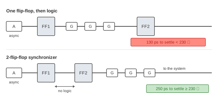
Real resolution times are random. The chance that a flip-flop is still unsettled after time t falls off as e−t/τ, where τ is a few picoseconds in a modern process. So the synchronizer does not make failures impossible; it makes the mean time between failures grow exponentially with Tc − t_setup, from microseconds to many years. The price is one cycle of latency. Sequential Logic shows how a flip-flop is built and why sampling a changing input can leave it stuck in between.
What the page leaves out
- Real delays depend on the load, the wire length, rising vs falling edges, voltage and temperature; static timing tools check every path at several corners. The page uses one t_pd and one t_cd per gate.
- A real block has thousands of paths; the page draws only the longest and the shortest.
- Clock jitter, clock trees, useful-skew optimisation, latches with time borrowing and multicycle or false paths are not modelled.
- Metastability resolution is random; the page uses a fixed t_res of 230 ps to stay repeatable.
References
Sarah L. Harris and David Harris, Digital Design and Computer Architecture, section 3.5: Timing of Sequential Logic (setup and hold constraints, clock skew, metastability, synchronizers)
Static timing analysis (Wikipedia)
Metastability (electronics) (Wikipedia): synchronizers and mean time between failures